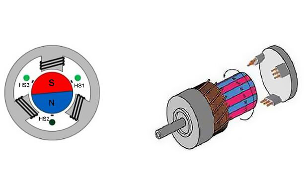
Hall sensor plays a role in brushless motors to measure the rotor pole position and provide the correct phase change information for the logic switching circuit, i.e. conversion position information, also referred to as a sensed brushless motor. The rotor pole bite is synthesized into an electrical signal, which then controls the stator winding to change phase. There are many types of position sensors, each with its own characteristics. There are three types of position sensors commonly used in brushless motor manufacturers: electromagnetic position sensors, magnetic position proximity sensors, and photoelectric position sensors.
In DC brushless motors, open-circuit transformers are widely used in electromagnetic position sensors. The open circuit transformer of a three-phase brushless motor consists of a stator and a tracking rotor. The stator usually has six magnetic poles, which are spaced 60 degrees apart. Three poles are wound with primary windings, connected in series, to a high-frequency power supply. The remaining three poles are wound with secondary windings WA, WB, and WC, respectively.
The magnetic position sensor is a semiconductor sensor whose electrical parameters change according to certain laws with the change of the surrounding magnetic field. The basic principle is the hall effect and magnetoresistive effect. Commonly used magnetic sensors include hall elements or Hall integrated circuits, magneto resistors, and magnetoresistive diodes.
The magnetic position sensor is a semiconductor sensor whose electrical parameters change according to certain laws with the change of the surrounding magnetic field. The basic principle is the Hall effect and magnetoresistive effect. Commonly used magnetic sensors include Hall elements or Hall integrated circuits, magneto resistors, and magnetoresistive diodes.
How is the DC brushless motor Hall sensor position determined?
It should be noted that the correct position is determined by the method presented here considering only the magnetic field generated by the rotor permanent magnet, i.e., the no-load magnetic field case. When a brushless motor needs to work in forward and reverse, this position is the most suitable one to make the motor perform consistently in forward and reverse. In fact, under load, there is a displacement of the magnetic field to zero point due to the distortion of the air gap magnetic field by the armature reaction. The armature reaction magnetomotive force shifts the most suitable commutation point forward, and strictly speaking, the sensor position determined by the no-load magnetic field is no longer the most suitable.
In fact, the correct determination of the position sensor position is also related to the following factors: the sensor's own characteristics, polarity regulations, the main motor stator and rotor structure, stator winding structure (such as phase band, coil winding direction, the number of short distance, double or single layer, etc.), the main motor rotor and sensor rotor relative position relationship, as well as the controller logic design, so it must be agreed first. The method proposed here is able to resolve the above complications and determine the correct position of the Hall position sensor in a relatively simple way.