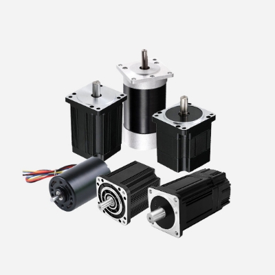
With the more and more widespread use of DC brushless motors, its performance has also improved to a certain extent. However, various failures will also be encountered in the process of using the BLDC motor, among which the inability to start the device is one of the most common problems.
What causes the brushless dc motor to fail?
Power loss
Reason
- The power switch of the connected device is not turned on properly.
- The front fuse is blown. The fuse of the motor main circuit or control circuit is blown.
- The power control devices such as contactors are out of order and the line wires are broken or loose.
Solution: Starting from the front-stage fuse, check the wires and devices of each part of the primary circuit and control circuit of the motor step by step, find out the cause and repair it.
Motor failure
Reason: BLDC motor failure is caused by poor contact between the brush and the commutator due to serious brush wear and insufficient spring pressure.
Solution: Disconnect the resistance gear of the multimeter of the power supply to check the contact resistance between the brush and the commutator caustic, find the cause and solve it in time.
Mechanical failure
The mechanical equipment or transmission mechanism of the motor is stuck, and the starting load is too heavy. At this time, the power supply should be cut off quickly and the mechanical fault should be found.
In addition to the above, other problems will be encountered that cause the brushless DC motor to fail.
1. The BLDC motor does not turn.
- If the voltage is insufficient, test whether the voltage of pin 3 of the MCU is greater than 3.2V.
- The brake level connection is normal, check the seventh pin of the MCU, as long as the voltage of the high-level brake is higher than 2...5V, and the voltage is lower than 2..5V during low-level braking.
- Whether the speed control voltage is applied to pin 5 of the microcontroller.
- Improper installation of the connector and lack of phase lead to output failure.
- When all the above conditions are met, the output and drive circuits fail, and the motor is forced to rotate by an external force. When there is obvious uneven resistance inside, most of them are damaged by the mos power tube, but some are damaged by the previous driving triode.
2. The motor rotates, but not normally.
- Whether the 60-degree and 120-degree working modes of the controller correspond.
- The ability of motor to rely on external force, there is a lot of noise when rotating, unstable output phase loss, check the connecting line, the components on the circuit board have leakage soldering, false soldering, short circuit, wrong soldering, etc.
- The Hall signal is wrong, and some motors need to adjust the controller output line or the Hall signal line.
- The motor is unstable when rotating at low speed, mostly because the parameters of the drive circuit components are too different, and the three-phase drive components are poorly tested and welded, resulting in poor performance.
3. The brushless motor is easy to stop and the load capacity is poor.
- The short-circuit comparison resistors R9 and R10 of the controller are 20K or 1.2K.
- The capacitance deviation of capacitor C7 (1000Pf) and dead zone adjustment capacitor C24 (100PF) is too large.
- Some components of the drive circuit leak, and the performance is poor.
4. The current limiting resistor heats up and the quiescent current is too large.
- There is a short circuit in the circuit.
- Whether the drive output is mis-soldered.
- The plug-in connection is corresponding.