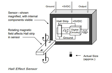
A hall current sensor is essentially a sensor based on the principle of hall current. When a conductor or semiconductor with current flowing in one direction is introduced perpendicular to the magnetic field, the current that obtains a measurable voltage is called Hall current. Simply put, when a magnetic field is applied in a direction perpendicular to the flow of current, a voltage is created across an electrical conductor. A Hall current sensor is a solid-state device that applies this principle to determine the position, velocity, and various other properties needed to effectively operate a brushless DC motor.
How do Hall current sensors work in brushless DC motors?
Typically, a high-speed BLDC motor will have three hall current sensors mounted on the rotor or stator. These hall sensors are placed 120 degrees from each other, providing angular positions from 0 to 360 degrees. When these Hall sensors come into contact with the rotor's magnetic field, corresponding digital pulses of 1s and 0s are generated, as shown in the figure below.
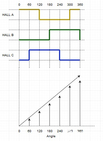
Through six steps, these Hall sensors are able to give the motor position (angle). In the figure, the rectangular waveforms show the positive and negative pulses produced by all three Hall current sensors A, B, and C at the corresponding angles. The corresponding diagram also shows how a reversal is done in 6 steps when the angle reaches 360 degrees.
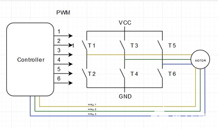
When the rotor magnet passes through one of the sensors, it produces a low or high signal, depending on whether the north or south pole of the rotor is passed. As the rotor passes through all three sensors, these switches between low and high positions, giving the rotor's position every 60 degrees. The figure below shows a typical BLDC motor controller. The three wires from the motor to the controller depict the signals sent by the three Hall current sensors.
Hall current sensors are able to distinguish between positive and negative charges moving in opposite directions. The magnetic field detected by the Hall current sensor is converted into a suitable analog or digital signal that can be read by an electronic system (usually a motor control system).
Shown below is a truth table derived from the readings of the three Hall current sensors. As you can see, the transistor state of the H-bridge depends on the signal detected by the sensor. Down arrows indicate clockwise motion (CW) and up arrows indicate counterclockwise motion (CCW).
| Hall A | Hall B | Hall C | Transistor State | |
| 1 | 0 | 0 | T3 | T2 |
| 1 | 0 | 1 | T6 | T6 |
| 0 | 0 | 1 | T6 | T6 |
| 0 | 1 | 1 | T4 | T4 |
| 0 | 1 | 0 | T4 | T4 |
| 1 | 1 | 0 | T2 | T2 |
Now that we have the truth table and graph, the angle (position) and speed of the rotor can be easily calculated.
1. Angle calculation: Calculated according to the Hall current sensor signal. Based on the Hall sensor pulses, the 0-360 degree angle is calculated.
2. Speed calculation: The speed calculation is done by calculating the period of the Hall current sensor signal. With the help of the period, the frequency and speed are calculated according to the following formulas. frequency = 1/ cycle.
Only one Hall sensor is needed to calculate the speed.
Advantages of using Hall current sensors in BLDC motor
- A Hall current sensor is a very simple device consisting of a magnet and thus very cost-effective for motor control systems.
- For the same reason, these sensors are easily implemented in advanced motor control systems for electric vehicles and other automotive solutions.
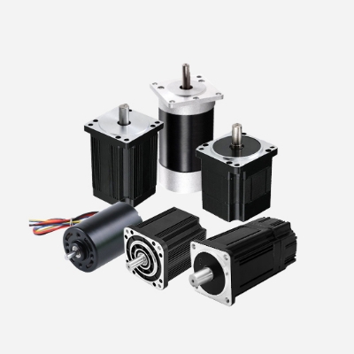
- Most BLDC motors are equipped with these sensors.
- Most of the Hall current sensors are not affected by environmental conditions such as humidity, temperature, dust and vibration.