What is a brushless motor stator?
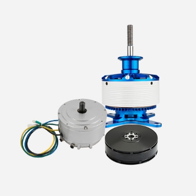
The stator of a brushless motor is the part that generates the rotating magnetic field and can support the rotor to rotate. It mainly consists of a silicon steel sheet, enameled wire, bearing, bracket, etc.; the rotor can support rotor rotation under the action of the stator rotating magnetic field, and the parts mainly consist of the rotor shaft, magnet, bracket, etc. In addition, the number of pole pairs formed by the stator and rotor will also affect the speed and torque of the motor.
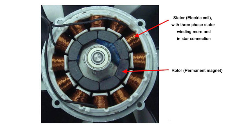
The stator of a brushless DC motor is a coil-wound armature and the rotor is a permanent magnet. By detecting the position of the motor rotor in real time and then providing the corresponding current to different phases of the motor according to the rotor position, the stator generates a rotating magnetic field with uniformly changing direction and the motor can rotate with the magnetic field.
The simplified logical structure of the brushless DC motor is as follows:
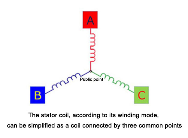
Brushless DC motors change the way A, B and C are energized, and the coils produce a rotating magnetic field, which drives the rotor to rotate.
A Brushless motor stator can not be separated from the winding, winding also pays attention to the skills and methods, in general, different stators, winding way more or less different, mainly according to the stator parameters to decide.
With the continuous development of science and technology, brushless motors are becoming more and more mature, the scope of application is becoming more and more extensive, replacing the traditional manual and semi-automatic mode, and winding equipment is also becoming more and more advanced, for brushless motors, currently common for the flying fork winding machine and needle winding machine.
Brushless motor stator winding method
Slot towards the outside of the stator, with more flying fork winding equipment, debugging should pay attention to adjusting the position between the die head, die tongue, stator rod, guard plate, positioning should be accurate, there can be no offset, there can be no jumping, broken wire, injury wire.
In the slot facing the inland stator, with more needle winding equipment, debugging should pay attention to the location and positioning between the wire arrangement device, needle rod, wire nozzle, stator skeleton, and mold, so as not to collide with the needle, the way of alignment should be reasonable and simple, the wire arrangement meets the requirements, there can be no broken wire, wounded wire.
Ordinary stator lining, for this requirement, is not very high, ordinary lining, with general equipment, can be, the configuration can be matched according to demand, after winding, good saltwater test, to determine the product meets the requirements.
Stator precision lining, precision lining requirements are higher, for spare parts, servo motors and drives have certain requirements, ordinary equipment can not meet the requirements, it is recommended to use a better configuration of the equipment, debugging to be careful, the line can not be chaotic.
Stator thick line, thick line is more difficult to adjust badly is easy to hurt the line, debugging speed to try to slow down a little, especially the bending place, winding way to try to simple, machine configuration to be better, pay attention to do a good brine test.
Multi-line and winding, depending on the specific circumstances, mainly depending on the size of the wire diameter, if the number of strands is relatively large, the wire diameter is also relatively large, for the configuration and winding method are to pay attention to, the speed must not be too fast, to avoid injury to the line situation.